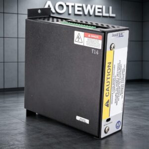
Allen Bradley 1503VC-BMC5 /E IntelliVAC Vacuum Contactor Control 1503VCBMC5
Allen‑Bradley 1503VC‑BMC5 Ser.E IntelliVAC Contactor Control Module Parameter Table
Basic Information
| Item | Specification |
|---|---|
| Part Number | 1503VC‑BMC5 |
| Series | IntelliVAC |
| Series Revision | SER.E |
| Manufacturer | Rockwell Automation / Allen‑Bradley |
| Origin | Made in Canada |
| Certification | CE, cRUus Listed |
Rated Supply Voltages
| Power Type | Range | Frequency Note |
|---|---|---|
| AC Input | 110…240 V RMS | 50–60 Hz |
| DC Input | 110…250 V DC | — |
Supply Current
| Current Item | Rating | Remark |
|---|---|---|
| Idle Current | Max 125 mA | Normal standby state |
| Inrush Peak Current | 25 A peak | No external capacitor required |
| Sealed Capacitor Current | Max 1.0 A | Internal capacitor circuit |
External Capacitor Terminals
| Pin No. | Definition |
|---|---|
| 1 | Negative (-) |
| 2 | Positive (+) |
Contactor Interface Terminal Definition
| Pin No. | Function | Description |
|---|---|---|
| 3 | Coil 2 COM | Common for trip coil (mechanical latch) |
| 4 | Coil 2 | Trip coil terminal |
| 5 | Coil 1 COM | Common for close coil |
| 6 | Coil 1 | Close coil terminal |
| 7 | Open Command + | Positive open command input |
| 8 | Open Command – | Negative open command input |
| 9 | Close Command + | Positive close command input |
| 10 | Close Command – | Negative close command input |
Command Voltage Range
- DC Command: 50 V … 250 V DC
- AC Command: 100 V … 240 V AC
Terminal Note
Command signal assignments will change under DeviceNet control or multi‑contactor mode; refer to official user manual.
Auxiliary Contact Terminals
| Pin No. | Function | Restriction |
|---|---|---|
| 11 | Auxiliary Contact | Do not feed external power to these pins |
| 12 | Auxiliary Contact | Do not feed external power to these pins |
Contactor & Module Status Outputs
| Pin No. | Signal | Electrical Load Capacity |
|---|---|---|
| 13 / 14 | Module Status | 250 V AC, 5 A resistive load
30 V DC, 5 A resistive load |
| 15 / 16 | Contactor Status | 250 V AC, 5 A resistive load
30 V DC, 5 A resistive load |
Other Specifications
- Configuration: DIP switch parameter settings printed on inner side of module cover
- Warning Marking
- DANGER label: Hazardous voltage exists inside; de‑energize power before removing cover, cover must stay installed during operation
- CAUTION label: Module pre‑configured at factory; verify all settings before energizing, improper configuration will damage equipment, remove this label to access power terminals
- Mechanical Structure: DIN rail wall mount metal housing, top terminal plug connector, dedicated Module Status indicator window
- Internal Mark: T14 internal production marking, serial number label affixed on side housing